Wednesday, 12 September 2012

Fingers on the pulse....

It's been a long time since I had any time to sit down and do anything else other than read about ship airwakes, plot ship airwake CFD data, then read more reports on bluff body aerodynamics. Progress on the dashboard has slowed considerably, to the point that hardly anything has happened since the last update other than I drilled some holes in a project box to fit the various electronic boards.
In other news since work on the dashboard has ground to a halt because I am stuck at uni during the week and at my girlfriends during the weekends I have been taking an interest in resuming work on pulse detonation engines or PDE's.  I amassed a fair bit of research on these engines with the idea of using a small two-stroke piston engine as a valve, somewhat similar to this patent, dated 2005 which is incidentally around the time when I was doing my research and struggling to use rubbish TurboCAD program to develop a some 3D models.
These engines are similar to pulse jets in the fact that combustion takes place intermittently and superficially they look alike but in the pulse detonation engine combustion takes place at high speeds. So high in fact that it produces a supersonic pressure wave that combusts the air/fuel charge almost instantaneously. Although in pulse jets and car engines the combustion process might seem to occur very quickly, it does in fact undergo a process called deflagration where fuel combustion propagates subsonically. Occasionally car engines and pulse jets can transition from deflagration to detonation and when this occurs a great deal of damage often occurs.
Anyway I abandoned the project quite early on, despite the relatively easy fabrication such an engine will require, the high precision required to control the engine made it a non-starter as I had no experience or understanding of control systems and the accompanying mathematics. Roll on nearly ten years and I find myself looking at another heap of reports and running some simple CFD simulations in between my PhD work and thinking this is a viable project. I should finish the Ardour dashboard too, but all my extra curricular activities will probably be on hold until I move house in a couple of months time... But I can still throw some time into designing the engine.
I've already decided that instead of using a valved PDE, my design will be valveless. I see point in going down the valved route as this requires high pressure fuel and oxidiser feeds, careful valve and ignition timing and would hardly make a lightweight, flight capable engine. The valveless route means I can use ambient air for the oxidiser, remove some complexity and reduce overall engine mass and cost, which is makes it attractive to a poor student like me. It's not all advantages though, it has a drawback. A big one. Without mechanical valves there is nothing preventing air or more specifically hot combustion gas from escaping from the engine without contributing to thrust. But all is not lost as you'll see soon enough, but more on that later, I still have to wait on some CFD results before I can move forward.

Saturday, 7 July 2012

Focus Magazine makes a cock up...

Bought a copy of Focus from Tesco's earlier because I was bored and I don't mind reading a bit of pop science now and then.. Anyway trudging through the questions and answer sections and I came across this nugget of misinformation. A question about setting a firework off on the Moon,  I'm sure any GCSE student could answer. But no... An astrophysicist made a boo boo.
Fireworks are mixtures of combustible fuels mixed with an oxidiser, for example black powder, I have made this myself and is a mixture of potassium nitrate, sulphur and charcoal. I mean who hasn't it's so easy and it is still the fuel of choice for small model rocket and firework motors. The potassium nitrate is the oxidiser, while the charcoal is the fuel, the sulphur just helps the reaction along. But this mixture will burn in a vacuum, on the Moon, in my hand, under my backside, in a rocket motor, in a cannon, under water, (providing the powder doesn't get wet)... 
So much for 'The Experts' who answer questions...

Wednesday, 4 July 2012

PWM Servo Control

Another short blog post, but I have drank almost an entire bottle of wine and I have a stack of papers to read about CFD analysis on ship air wakes. Haven't started the PhD yet, and although PhD's don't officially start till October, I'm needed to start as soon as possible. So rather than spend the first week trying to play catch up, I have been reading everything and anything on the subject so that I can hit the ground running. In other news, I have also bitten the bullet and ordered a second µChameleon DAQ, so that means I have up to 16 analogue channels, which means I can add other sensors in time as I'd like to take more pressure readings, especially the combustion chamber pressure loss and the pressure drop across the turbine stage.

I have been playing with the µChameleon DAQ to try and control an RC servo by providing a PWM output. The µChameleon has two 5V outputs, allowing me to power the servo directly, while channels 9 to 12 are the PWM output channels. It didn't take as long as I expected. Some to the examples provided by Labview looked complex and where composed of lots of sub vi's. I have no doubt that these would work, but since I don't have access to an National Instruments DAQ I couldn't find out. So I played with the VISA functions and managed to get a simple PWM servo controller to work in about an hour. I only needed to mimic a PWM signal given by a radio control receiver from a full throttle input signal. Once again the trusty oscilloscope came in handy. The pulse width values I have used, (the two constants on the left in the diagram), corresponded to maximum and minimum values I found for one of my radio control system. This value doesn't really need to be specific as the gas turbine ECU can be adjusted to read the max/min values of any radio control system and set the throttle range accordingly. I then convert the range between the two values into a percentage and multiply that with the throttle input value. Although a hundred steps seems a bit coarse, the average radio control transmitter may only have twenty five steps, (if using a ratchet system on the stick), so a discrete range of a hundred steps should be more than adequate.
Most ECU's are also started by moving the throttle trim to max and cycling the throttle from idle to max and back to idle, once the ECU see's these throttle movements it initiates the start up procedure. I intend to replicate this by having the start button on the dashboard input a 10% throttle input into the ECU replicating the maximum trim position.

Monday, 2 July 2012

Success!!!

I have been formally offered a place on the PhD project I applied for, Ship Design Guidance for Aircraft Operations!
That is all.

Monday, 25 June 2012

Dashboard Update

Haven't been in the mood to do much today so I spent a couple of hours tidying up my dashboard. I changed to the 'old' style gauges to some sharper ones and now it looks a bit more slick. I have also rigged up a switch to start recording data which is sent to a text file. I can then open this in Excel for further analysis letting me analyse the results easily. Prior to this I'd have to calibrate all the channels I used on the DAQ then start the engine and perform the experiment, then find the chunks of data that relate to the experiment for channel 1 and so on.. This way I have all the channels I want to analyse exported as a chunk, and only for the time I want to capture.
I am nowhere near to finishing the block diagram yet, so when I do i will make that available too. I need to write some functions to calculate efficiencies and a lookup to find the air massflow rate. Think I will tackle the PWM throttle signal next as the turbine flowmeter I have been waiting for will not be in stock till November!! Nice of the company to keep that quiet after I had ordered and paid for it nearly three weeks ago and only told me after I had sent an email Asking me if I wanted to cancel or wait. Yes I think I will be cancelling that order! I'm not waiting five months I'll have to order a slightly more expensive one from EBay.

Sunday, 24 June 2012

It's not rocket science... Oh wait, yes it is..

In other news, a friend from uni has expressed interest in starting a small experimental rocket team to get a micro-satellite into low earth orbit, so far there around five students who expressed interest but just the two of us who actually want to get anything done. It seems that once again that the engineering students I know are all too interested in a well paid career than having any kind of affinity for engineering. Anyway a task of this magnitude would take many years, but who's to say it will never happen, all big projects had to start somewhere and other teams like Ausroc, Aspire, dutch Sub-Orbitals, Starchaser and SpaceX all started with a few interested people and big ideas. We have planned out initial project aims of building a small scale version of the liquid fuelled rocket engine, on the order of 1000N, and to have reached an altitude of 5km by December. The highest I have been before was about 1.5Km and that was with a commercial solid fuel motor and rocket this is going to be something else entirely. We have begun to put out some tentative feelers about who and how to start applying for funding or sponsorship. I have enough equipment, instrumentation and materials from previous projects to build and test a fairly large proportion of this initial stage, but there's no way we can afford the rest on our own budgets. Let alone the further stages of the project should we actually meet the objectives.

 
Talking of funds, well it looks like my bank account is going to take another hit because I need to buy another DAQ... Luckily with the European economies they way they are, I will be able to shave a bit off the the price. I need it because I have ten analogue signals I need to measure and thought I could use both the µChameleon and a DATAQ DAQs, but this has proved to be messy and it conflicts with my desire for everything to be symmetrical... This will also help in that I can monitor the gas and fuel solenoids, starting motor and glow plug operations easier, than trying to read these through the digital I/O channels.

Everything is coming together well now, I am starting to think about the physical test bench. I have some plans I sketched out a couple of years ago that involved the test bench mounted on a trolley with the engine operating inside a fully enclosed 'box' with the exhaust ducted out the rear. Fuel and instrumentation would be housed in separate compartments. This has the benefits of reducing noise, I know it won't be much, but even a few decibels would enough to help reduce the annoyance to the neighbours. I only wear ear defenders for the full throttle runs because I love engine noise, even high pitched rasping two-stroke engines! Another plus for this isolated engine layout, is the fact I can easily inject CO2 from a fire extinguisher should the need arise and it has on many occasions. I have set fire to the shed, my parents shrubbery, myself, in fact anything can be burned has been burned over the course of my life. The shrubbery is a particularly sore point with my mother who brings it up with anybody and everybody more than ten years after the incident. To be fair I really didn't think the exhaust from a small jet engine, without an exhaust nozzle, would be hot enough at ten feet to cook an entire bush. But I was wrong, and to top it off a bearing failure at 80,000 RPM then left pools of burning kerosene on the new block paving. I got the feeling I wasn't her favourite person that week.

Currently the dashboard in Labview looks like this. I'm still not happy with the layout, but it's getting there. Apologies for the mixture of metric and English units, That's if you noticed the temperature meters were in degrees Centigrade rather than Kelvin. I will be using this to monitor the engine in real time and my brain works best in Centigrade, especially at the higher combustion temperatures, because its the unit I use most in daily life. I only work with Kelvin when mathematics are involved. It's a bad habit I know, but I don't want to run the risk of missing something going wrong a moment before all hell breaks loose because I was confused with subtracting 273 degrees. Despite having just done a maths degree in disguise, it seems I am hopeless at simple arithmetic. I've also christened the project Ardor which is Latin for flame, burning, heat..... according to my seventeen year old, high school Latin dictionary. After my track record in testing gas turbines, I think the name is justified. There's still some things that need to be added to the dashboard, but these are simple indicators to notify me when the ECU is cycling through various start up systems. The next big job is figuring out how to export a PWM signal and adding a second vi to control another DAQ.

Judging by the amount of blog traffic I get just from people looking how to measure RPM in Labview, there must be some interesting projects out there. If you're doing something interesting let me know! I love reading about what other people are up to!

Friday, 15 June 2012

Signal Conditioning

I have been having some issues with noisy outputs from the µChameleon DAQ so when running the dashboard to see how well my sensors and their associated circuitry performed. The voltages I'd measure on a multimeter were fine, however Labview would show wildly fluctuating signals which had the needles on the gauges jumping over very large values. If you look at my previous Labview vi's you might notice that I had tried to lessen the effects of this unknown noise using a simple mathematical method where I limited the number of decimal places of the number string. I had tried to do some fault finding a few weeks ago and didn't really get anywhere as I didn't yet have an oscilloscope, but it now seems I have fallen victim to the dreaded aliasing...

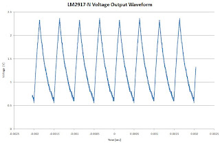
Looking at the RPM voltage signal on the oscilloscope showed not the linear voltage I was expecting, but a triangular waveform that had a mean voltage that was the same what I was seeing on the multimeter. The maximum to minimum voltage was in the region of 1.8V!!! Which, after figuring out the scale I'd used, corresponded to the magnitudes of the needle fluctuations I was seeing in my Labview gauges.

That was one mystery solved, but why was the DAQ giving me a signal that looked like random noise. Now when I bought the DAQ I noticed it had a sample rate that was more than sufficient, at 50KHz. Even if it only ever realised 60% of that claim it would be more than fast enough, can you see where this is going? It does indeed seem that you get what you pay for, and in my case that would be a measured sample rate of around 50HZ on my analogue channels which is only 0.1% of the claimed sample rate. Some digging on the products help forum showed similar results from other people, although it seems like the moderators don't keep on top of the spam robots which seem to have flooded the site when I checked it a couple of days ago. Putting this into context, at 50Hz the time step between each sample is 0.02 seconds, as you can see in the graph of the waveform above, the period of that signal is 0.0005 seconds. This means that the DAQ cannot capture the waveform and the result is a signal that looked noisy. Incidentally, if I had a sample rate of twice the measured frequency, Nyquist theorem, then I'd need a sample rate of 10KHz.

Putting this together it seems like the low sample rate and the noisy waveform was the source of my frustrations. Even if the DAQ had a higher sample rate and aliasing wasn't a problem, the values would still oscillate and I'd still have data which would be unusable. I looked at commercial signal conditioning, but after a few seconds the cost and complexity had me running for coffee and an easier solution. Digging out some of my uni notes from a third year module, I found that I might solve the problem using a filter, specifically a 'Low Pass filter', this comprises of a capacitor and a resistor. Couldn't be simpler, so literally a few minutes later I had found that a 1MΩ resistor and a 220nF capacitor reduced the magnitude of the noise from 1.8V to 0.3mV and the noisy behaviour of the Labview gauges had stopped. Finally!!


Now that I have sorted the noisy signal issues I have also been able to implement Labviews built in Thermocouple vi  to interpret the temperature from the thermocouple. This saves me from creating a large lookup table to locate the temperature value based on the voltage. Previously I have been using a quick and dirty method to estimate the temperature based on the product of a simple conversion factor and the voltage. I did a test where I dunked a couple of digital thermometers into a cup with one of my thermocouples and monitored how it performed by watching the temperature drop of boiling water and observing the values. I'm happy to say that the temperature my thermocouple was giving values within 1°K of the food grade thermometer than the thermometer that I use to monitor one of my aquariums. Looks like I won't be using that one in my reef tank anymore.

Still have to sort out my load cell, pressure transducers and flowmeter, but things are coming together quite quickly now. Stay tuned!