Remember a few months ago I mentioned how I was planning on using Labview to display the engine speed by splitting the signal between the Hall sensor and ECU. Now I had tried to simulate and convert a square wave in Labview to represent the engine speed, and didn't really have much success. I had an idea whereby I converted the frequency of the signal into a voltage and treated it the same way as the other signals. Now after looking at trying to do this in Labview, which lead me to almost scrapping the idea of using Labview and instead toyed with the idea of writing the whole thing using Python which I gave up. The madness continued and I looked at writing some code in Matlab and trying to get Labview to utilise the code to analyse the signal and spit out the RPM... This was starting to get complicated, so I wondered if I could solve this with an analogue solution. A quick Google and one coffee later I had found an IC from National Instruments that would do this, and that was as far as I got.
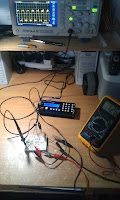
Fast forward a few months and I have just finished a prototype circuit, tested it and it seems to be stable and working fine. I have yet to test it with the DAQ and Labview, but that's a mere formality. I apologise for the messy picture showing the prototype circuit, I will transfer this to Veroboard shortly and tidy it up a bit. Just incase you can't match the circuit diagram with the circuit on the right I have numbered the important features that might need highlighting because there is a lot of crocodile clips in there. My new oscilloscope and function generator have been invaluable in this mini-project, so much that I think I would have abandoned it long ago if I didn't have them.
The corresponding circuit diagram which is based on the prototype circuit looks like this, not too bad for something I knocked up in Microsoft Paint!
You might have noticed the addition of an adjustable voltage regulator, this is to modify the pulsed DC signal given by the Hall sensor into an AC signal that can be read by the LM-2917 chip. After getting the circuit performing nicely giving a 0V to 4.5V output for 0 to 3KHz, which is 180,000 RPM I started playing with the input square wave to approximate the signal that I'd actually need to measure instead of a sinusoidal wave. At this point I found out that this chip doesn't like pulsed DC signals. Here is some data I took from the Hall sensor, at 88Hz showing the signal. As you can see, the signal is offset and doesn't cross the zero volt axis. Therefore I just simply added any voltage between -0.5V and -4V to the input signal to ensure that it crosses the zero volt axis and therefore can be read by the NI chip. In the end I used -1.5V, produced by a voltage regulator that I got from Maplins for £0.85. The polarity of the voltage regulator doesn't matter, if you want to shift the wave below the axis you can either add a positive voltage to the ground side of the waveform signal or add a negative voltage to the positive side of the signal.
 I'm sure there is an easier way to read the RPM in Labview, I did think about hacking the ECU itself to read the voltage from its frequency-voltage converter chip, assuming it has one but I don't want to risk introducing noise into the ECU that could lead to it destroying a turbine. These engines will self destruct in a very, very short time especially at high RPM's. Besides, I don't know about you, but sitting in front of this isn't a bad way to spend a few hours!
 Just a quick note on the oscilloscope, It's an Atten ADS1102CAL 100MHz and I got it off EBay for about £190 and it is very good value for money and has more than enough capability for what I need to do. After using CRT style oscilloscopes in the past, this is super light and compact and very unobtrusive in my small room.


